Ferrocement, also written as ferrociment, ferrocemento, ferrocimento, and ferrozement, literally mean much steel rather than much concrete. The Committee 549 of the American Institute for Concrete submitted the following definition of the ferrocement subsequently adopted by the majority of the specialists: " The ferrocement is a type of reinforced concrete in thin elements currently constituted by micro) concrete of hydraulic cement reinforced with thick layers of continuous netting, in wire with a relatively small diameter. The net may be metallic or in other materials ."
A.E. Naaman defines ferrocement as reinforced concrete in guise of thin elements with
Point of contra flexure is assumed to be at mid-height of each column.
Point of contra flexure assumed to be at mid-span of each girder or beam.
Horizontal shear on each story is divided between columns in that story such that each interior column carries twice as much shear as exterior Column caries.
Cantilevers Method
Point of contra flexure is assumed to be at mid-height of each column.
Point of contra flexure is assumed to be at mid-span of each girder or beam.
Intensity of axial stress in each column of a story is proportional to the horizontal distance from the c.g of all the columns of that story.
Column Footing is also famous as independent footing. An independent footing is one which is provided under a column or either similar member for distributing concentrated load in the form of uniformly loads on the soil below. The footing may be square, rectangular or circular in plan. Depending upon the load to be carried and the bearing capacity of soil, this may be of brick masonry, stone, R.C.C., steel grill-age etc.
On account of low bending strength the footings constructed with brick, stone or plain concrete require considerable depth to be safe to carry heavy loads. The depth of plain concrete footing can be appreciably reduced by providing reinforcements at its base to take up tensile stresses. R.C.C. column footings may be circular, rectangular or square in plan. The footing is reinforced both-ways by means of mild steel ribbed bars placed at right angles to one another at equal distances apart.
A shallow foundation transfers building loads to the nearest earth surface, rather than to a sub-surface layer or a range of depths as does a deep foundation. Shallow foundations are usually embedded a meter or so into soil. One common type is the spread footing which consists of strips or pads of concrete (or other materials) that extend below the frost line and transfer the weight from walls and columns to the soil or bedrock. Another common type is the slab-on-grade foundation where the weight of the building is transferred to the soil through a concrete slab placed at the surface.
Deep foundations are used to transfer a load from a structure through an upper weak layer of soil to a stronger deeper layer of soil. There are different types of deep foundations including helical piles, impact driven piles, drilled shafts, caissons, piers, and earth stabilized columns. It ensures stability and durability of a structure. Historically, piles were wood, later steel, reinforced concrete, and per-tensioned concrete. Sometimes these foundations penetrate bedrock.
Traverse Surveying is a popular method of surveying. This article includes definition of traverse surveying along with its classification,errors in traversing, checks, the completed method of traversing and plotting of traverse survey.
DEFINITION
Traversing is that type of survey in which a number of connected survey lines form the framework and the directions and lengths of the survey lines are measured with the help of an angle measuring instrument and a tape or chain respectively.
Closed traverse: When the lines form a circuit which ends at the starting point, it is known as closed traverse.
Open traverse : When the lines form a circuit ends elsewhere except starting point, it is said to be an open traverse.
SUITABILITY
The closed traverse is suitable for locating the boundaries of lakes, woods, etc and for survey of large areas. the open traverse is suitable for surveying a long narrow strip of land as required for a road of canal or the coast line.
DIFFERENCE BETWEEN CHAIN AND TRAVERSE SURVEYING
Traverse survey differs from chain surveying in the arrangement of the survey lines is not limited to any particular geometric figure as in chain surveying, where a system of connected triangles forms the fundamental basis of the skeleton. Also, check lines etc. are not necessary in traverse as the traverse lines may be arranged near the details. The details etc. are directly located with respect to the survey lines either by offsetting or by any other method.
METHODS OF TRAVERSING
There are several methods of traversing, depending on the instruments used in determining the relative directions of the traverse lines. The following are the principal methods:
Chain traversing
Chain and compass traversing
Transit type traversing a)By fast needle method b)By measurement of angles between the lines
Plane table traversing
1.CHAIN TRAVERSING
The method in which the whole work is done with chain and tape is called chain traversing. No angle measurement is used and the directions of the lines are fixed entirely by linear measurements Angles fixed by linear or tie measurements are known as chain angles. The method is unsuitable for accurate work and is generally used if an angle measuring instrument such as a compass, sextant or theodolite is available.
2.CHAIN AND COMPASS TRAVERSING
In chain and compass traversing, the magnetic bearings of the survey lines are measured by a compass and the lengths of the lines are measured either with a chain or with a tape. The direction of magnetic meridian is established at each traverse station independently. The method is also known as tree or loose needle method.
3.TRAVERSING BY FAST NEEDLE METHOD
The method in which the magnetic bearings of traverse lines are measured by a theodolite fitted with s compass is called traversing by fast needle method. The direction of the magnetic meridian is not established at each station but instead, the magnetic bearings of the lines are measured with reference so that direction of the magnetic meridian established at the first station. There are three methods of observing the bearings of lines by fast needle method.
Direct method with transiting
Direct method without transiting
Back bearing method
TRAVERSING BY DIRECT OBSERVATION OF ANGLES
In this method, the angles between the lines are directly measured by a theodolite and the magnetic bearing of other lines can be calculated in this method. The angles measured at different stations may be either
included angles and
deflection angles
TRAVERSING BY INCLUDED ANGLE
An included angle at a station is either of the two angles formed n\by two survey lines meeting there and these angles should be measured clockwise. The method consists simply in measuring each angle directly form a back sight on the preceding station. The angled may also be measured by repetition. The angles measured from back station may be interior or exterior depending on the direction of progress.
In the Fig(a) the direction of progress is counter-clockwise and so the angles measured clockwise are interior angle. In the Fig(a) the direction of progress is clockwise and so the angles measured clockwise are exterior angle.
TRAVERSE BY DEFLECTION ANGLES
A deflection angle is the angle which a survey line makes with the prolongation of the preceding line. It is designated as right (R) or left (L) according as it is measured clockwise or anti-clockwise from the prolongation of the previous line. This type of traversing is more suitable for survey of roads, railways, pipe-lines etc where the survey lines make small deflection angles.
ERRORS IN TRAVERSING
The errors involved in closed traversing are two kinds:
linear and
angular.
The most satisfactory method of checking the linear measurements consists in chaining each survey line a second time, preferably in the reverse direction on different dates and by different parties. The following are checks for the angular work:
Travers by included angles:
The sum of measured interior angles should be equal to (2N-4), where N=number of sides of the traverse.
If the exterior angles are measured, their sum should be equal to (2N=4)p/2
Travers by definition angles: The algebraic sum of the deflection angles should be equal to 360°, taking the right hand and deflection angles as a positive and left hand angles as negative.
Traversing by direct observation of bearings: The force bearing of the last line should be equal to its back bearing ±180° measured from the initial station.
CHECKS IN OPEN TRAVERSE
No direct checks of angular measurement are available. So indirect checks can be made. As illustrated in the Fig(a) the addition to the observation of bearing of AB at station A, bearing of AD can also be measured., if possible. Similarly, at D, bearing of DA can be measured and check applied. If the two bearings differ by 180°, the work may be accepted as correct.
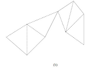
Another method, which furnishes a check when work is plotted is shown as in Fig (b) and consists reading the bearing to any prominent point P from each of the consecutive stations. The check in plotting consists in laying off the lines AP, BP, CP, etc and noting whether the lines pass through one point.
PLOTTING A TRAVERSE SURVEY
There are two principal methods of traverse survey:
Angles and distance method: This method is of three types. (a)By protractor (b)By the tangent of the angle (c)By the chord of the angle.
Co-ordinate method.
TRAVERSE COMPUTATIONS
In the figure, the latitude and the departure of the line AB of length l and reduced bearing q are given by
L= + l cosq and D=+ l sinq
To calculate the latitude and departure of the traverse lines, it is first essential to reduce the bearing in the quadrant system. The signs of latitude and departures will depended upon the reduced bearing of the line. The following table gives signs of latitudes and departures.
Table-1
W.C.B
R.B and quadrant
Sign of
Latitude
Departure
0° to 90°
NqE; I
+
+
90° to 180°
SqE;II
-
+
180° to 270°
SqW;III
-
-
270° to 360°
NqW;IV
+
-
Thus, latitude and departure co-ordinates pf any point with reference to the preceding point are equal to the latitude and departure of the line joining the preceding point to the point under consideration. Such co-ordinates are also known as consecutive co-ordinates or dependent co-ordinates.
It is hypothetical which represents frictionless flow i.e. fluid without any viscosity. It is also called inviscid fluid. In ideal fluid the internal forces at any internal section are always normal to the section, even during motion. Hence the forces are purely pressure forces.
b) Real fluid:
In a real fluid tangential or shearing force always come into being whenever the motion takes place, thus giving the rise to fluid friction, also known as viscosity.
2.
a) Compressible fluid:
Fluids which will change in volume with the application of force are known as compressible fluid. Gases are compressible.
b) Incompressible fluid:
It implies fluids with constant density i.e. it will not change in volume with the application of force. Though liquids are slightly compressible they are usually assumed to be incompressible.
3.
a)Newtonian fluid: A Newtonian fluid is a fluid whose stress versus strainrate curve is linear and passes through the origin. The constant of proportionality is known as the viscosity.
A simple equation to describe Newtonian fluid behavior is
Where
t is the shear stress exerted by the fluid [Pa]
µ is the fluid viscosity - a constant of proportionality [Pa·s]
is the velocity gradient perpendicular to the direction of shear [ s-1]
For a Newtonian fluid, the viscosity, by definition, depends only on temperature and pressure (and also the chemical composition of the fluid if the fluid is not a pure substance), not on the forces acting upon it.
b)Non-Newtonian fluid: A non-Newtonian fluid is a fluid whose flow properties are not described by a single constant value of viscosity. Many polymer solutions and molten polymers are non-Newtonian fluids. In a non-Newtonian fluid, the relation between the shearstress and the strain rate is nonlinear, and can even be time-dependent.
Viscosity:
The viscosity of a fluid is a measure of its resistance to shear or angular deformation. The friction forces in fluid flow result from the cohesion &momentum interchange between molecules in fluid.
Viscosity depends on temperature. But this property is different for liquid & gas. As temperature increases, the viscosities of all liquids decrease, while the viscosities of all gases increase.
Reason: This is because the force of cohesion, which diminishes with temperature, predominates in liquids, while with gases the predominating factor is the interchange of molecules between the layers of different velocities. Thus a rapidly moving molecule shifting into a slower-moving layer tends to speed up later. And a slow-moving molecule entering a fast-moving layer tends to slow down the faster-moving layer. This molecular interchange sets up a shear, or produces a friction force between adjacent layers. Increased molecular activity at higher temperatures causes the velocity of gases to increases with temperature.
Classification of flow
a)Laminar /streamline/ viscous flow:
It occurs when a fluid flows in parallel layers, with no disruption between the layers. The fluid appears to move by the sliding of laminations of infinitesimal thickness relative to the adjacent layer.
b)Turbulent flow:
The main characteristics of turbulent flow is its irregularity, there being no definite frequency, as in wave action, and no observable pattern.
a)Steady flow:
A steady flow is one in which all conditions at any point in a stream remain constant with respect to time, but the conditions may be different at different points. True steady flow is found only in laminar flow.
b)Unsteady flow:
An unsteady flow is one in which all conditions at any point in a stream do not remain constant with respect to time.
a)Uniform flow:
A truly uniform flow is one in which the velocity is the same in both magnitude direction at a given instant at every point in the fluid.
b) Non uniform flow:
A non-uniform flow is one in which the velocity is not same in magnitude or direction at a given instant at every point in the fluid.
a) Rotational flow:
It implies the flow where the fluid particles rotate about their own axis.
b) Irrotational flow :
It implies the flow where the fluid particles do not rotate about their axis, they only retain their orientation.
Other Definitions
Path lines:
It is the trace made by a single particle over a period of time.
Stream lines:
Streamlines show the mean directions of a number of particles at the same instant of time. Streamlines are a family of curves that are instantaneously tangent to the velocity vector of the flow.
Streak lines:
Streak lines are the locus of points of all the fluid particles that have passed continuously through a particular spatial point in the past. Dye steadily injected into the fluid at a fixed point extends along a streak line. These can be thought of as a "recording" of the path a fluid element in the flow takes over a certain period. The direction the path takes will be determined by the streamlines of the fluid at each moment in time.
According to the American Congress on Surveying and Mapping (ACSM), Surveying is the science and art of making all essential measurements to determine the relative position of points and/or physical and cultural details above, on, or beneath the surface of the Earth, and to depict them in a usable form, or to establish the position of points and/or details.
Surveying has been an essential element in the development of the human environment since the beginning of recorded history (ca. 5000 years ago) and it is a requirement in the planning and execution of nearly every form of construction. Its most familiar modern uses are in the fields of transport, building and construction, communications, mapping, and the definition of legal boundaries for land ownership.